In a previous article we have already defined what the phenomenon of cavitation consists of (link available at the end). In general, in a water park, the most frequent hydraulic conduits are the swimming pool filtration networks and the supply lines of water attractions such as slides, jets, etc. Both cases correspond to pressurised pipes with pumping systems. In this type of infrastructure, the areas most susceptible to cavitation are the high points in the pipeline route, the narrowing or sudden choking of the pipeline or the suction branches of a pumping system.
-At high points in a pipeline, when the pipeline path is above the pipeline piezometric line, negative relative pressures are reached. It is necessary to assess the pressure in the pipeline at these points, as vapour pressure could be reached and cavitation could be triggered.
Figure 1.
In Figure 1, two cases are shown where two tanks are connected by a pipe with a high point. In the first case, the piezometric line (green line) does not intersect the path of the pipe, so the high point (PA-1) is not susceptible to cavitation. However, at the high point of the second case (PA-2), the piezometric line of the pipe intersects the path of the pipe, so that in this area (area coloured in red) negative relative pressures are produced that could reach the vapour pressure and, therefore, trigger cavitation.
Suction valves are usually installed at these high points, which allow the venting of water vapour and air in the event of bubbles forming. In this way, bubbles do not hatch inside the pipe and damage is prevented.
-In the case of sudden constrictions or throttling of the pipeline, the water velocity will increase considerably, which will result in a consequent pressure drop. If the pressure drop is sufficiently large, the vapour pressure will be reached and cavitation will occur. Generally, this phenomenon occurs at very sharp reductions in cross-section or when partial closure of shut-off valves causes a considerable throttling of the flow area

Figure 2.
Figure 2 represents a pipe section in which the partial closure of a butterfly valve throttles the free passage area. The pipeline load line is shown in green and the piezometric line in orange. The latter shows the pressure drop in the throttling zone, due to the increase in fluid velocity.
-Let us look at the third case, that of the suction branches of a pumping system: in a pumped pipe, the area of lowest pressure is precisely in the suction branch, specifically in the suction flange section of the pump, which is where cavitation could be triggered. Cavitation in pumps is evaluated on the basis of the parameter called NPSH (Net Positive Suction Head), which corresponds to the net positive pressure at the suction flange of the pump.
The NPSH parameter available in the pipeline (or NPSHd), corresponds to the total pressure reserve above the vapour pressure of the fluid, and is calculated as follows:
-If the pump is under load:
[ NPSH_d = 10 ^ 5 · + H – ΔH_5 ] -If the pump is working on suction:
[ NPSH_d = 10 ^ 5 · – H – ΔH_5 ] Where:
NPSHd: Net positive pressure at the suction flange available in the pipeline (in metres).
Patm: Atmospheric pressure (in Bars).
Pv: Vapour pressure (in Bars).
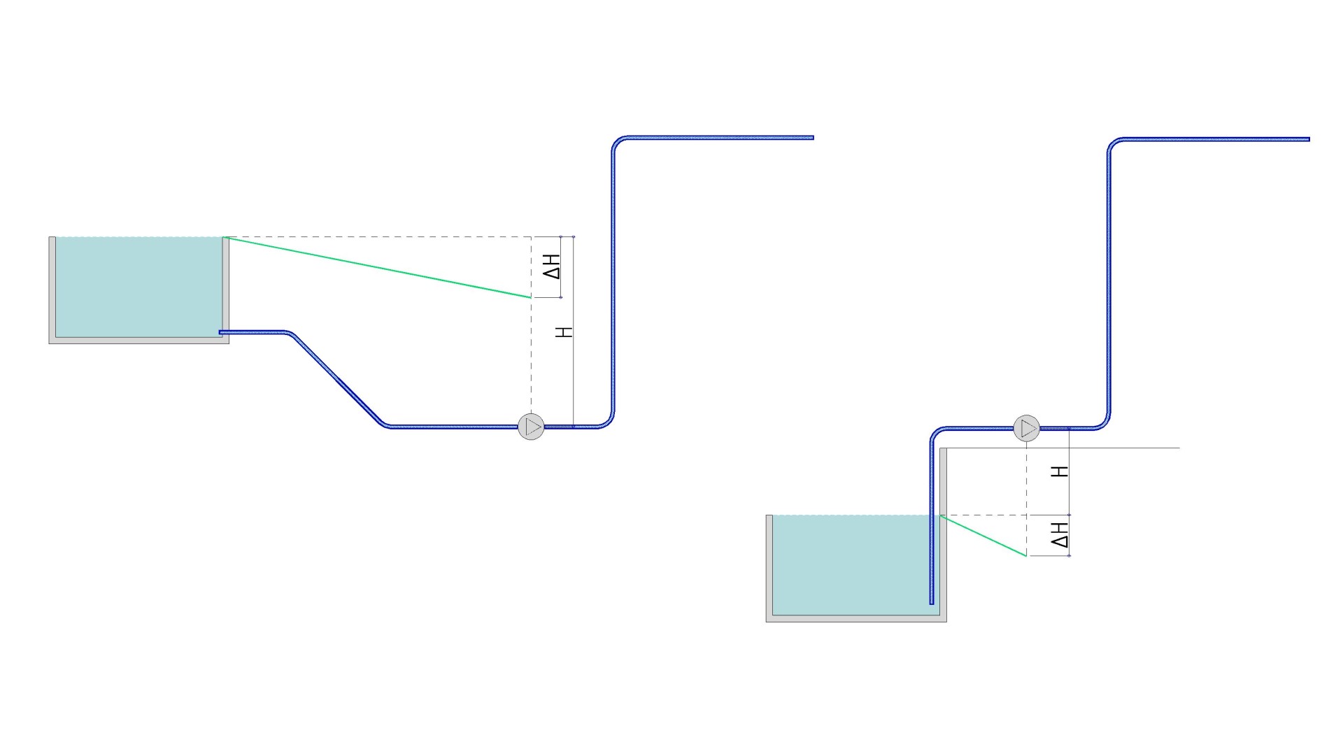
H: Gravitational potential energy in the suction tank (in metres).
∆H: Pressure drop in the suction pipe (in metres).
γ: Specific gravity of the water (Newton/m³).

Figure 3.
Figure 3 shows two suction schemes: on the left the pump is at load; on the right the pump is at suction. Obviously, in the second case, the NPSH is lower, so the possibility of cavitation is higher.
The NPSHd in the pipeline is compared with the minimum NPSH required (or NPSHr) by the pump in question. This last parameter, the NPSHr, is intrinsic to the pump model used in the system. It is guaranteed that there will be no cavitation in the pump if the following condition is met:
[ NPSH_d ≥ NPSH_r + RS ] Where:
RS: safety guard, the value of which is usually 0.5 m or 1.0 m.
In the water park projects it develops, Amusement Logic carefully studies these points in the hydraulic piping network. It is therefore able to guarantee that cavitation is not triggered at any of them. This ensures the correct functioning and durability of your hydraulic infrastructures.
You can access the definition of the cavitation phenomenon HERE.
By Luis Llor, Senior Hydraulic Engineer at Amusement Logic’s Architecture Dept.


