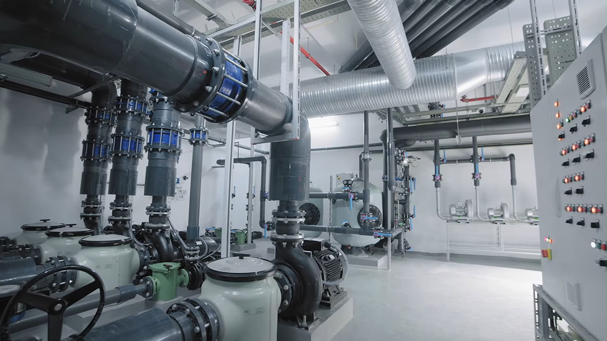
A variable frequency drive is a device that regulates the frequency and supply voltage of an electric motor and, through them, its rotational speed. Amusement Logic applies this type of device to centrifugal hydraulic pumps, related to swimming pools and water park attractions. To understand how they work, we need to know a number of definitions.
Resistance or characteristic curve of a hydraulic line
This is a representation of the energy requirements, in terms of head, for each flow rate flowing through a given pipe. It is an increasing quadratic relationship between head (H) and flow (Q), since the energy varies with the square of the flow. The function is of parabolic type, with an expression of the following type:
H = Hg + K·Q²
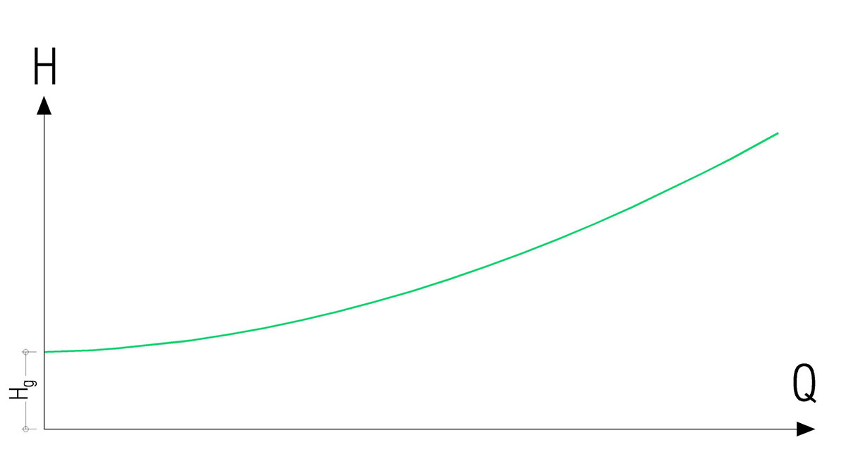
Resistance or characteristic driving curve
Driving curve of a hydraulic pump
This graphically represents the capacity of a pump to deliver a flow rate, in relation to the pressure during pump operation. It is a decreasing relationship between head (H) and flow (Q).
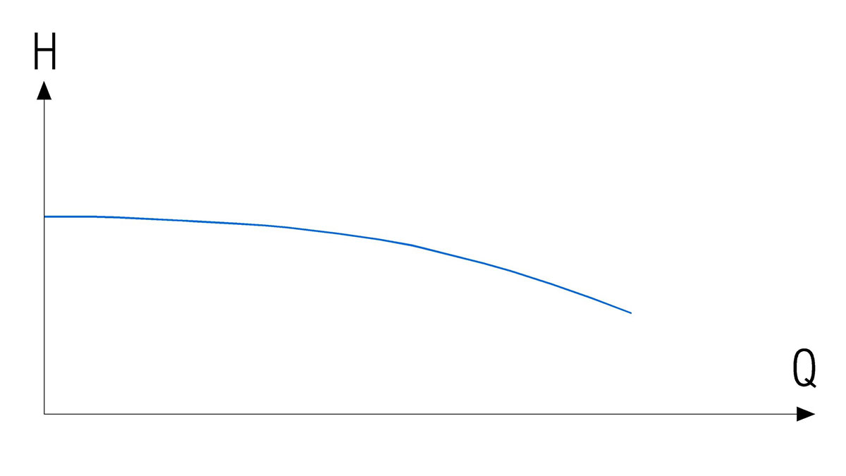
Pump drive curve
Water pump operating point
This is the cut-off point P (Q,H) between the driving characteristic curve and the pump driving curve.
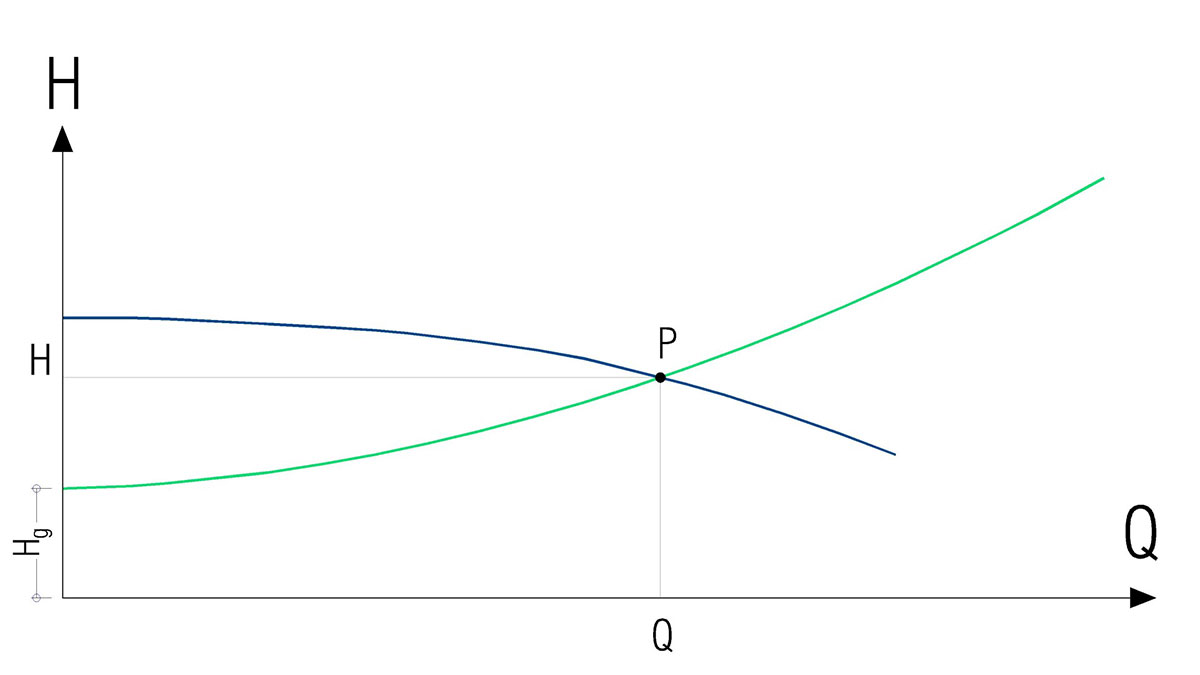
Operating point of a pump
We are now in a position to understand the effect of variable frequency drives on hydraulic pumps and the advantages they offer in the operation of water parks. Let’s see:
Effects of varying the rotational speed of the motor of a hydraulic pump
The pump’s characteristic curve is unique for each model and the variation in motor speed generates a parallel drive curve. An increase in rotational speed is represented by a parallel H-Q drive curve above the original curve. A decrease in rotational speed is represented by an H-Q curve below the original curve. Therefore, when a variable frequency drive is applied to a hydraulic pump, there is not only one drive curve, but a set of concentric drive curves, each one of them for a specific motor speed.
This allows the same hydraulic pump to have several different operating points. The following graph shows the set of driving curves of a pump for different rotational speeds (where ω1 corresponds to a higher rotational speed and ω4 to a lower one), regulated by the variable frequency drive.
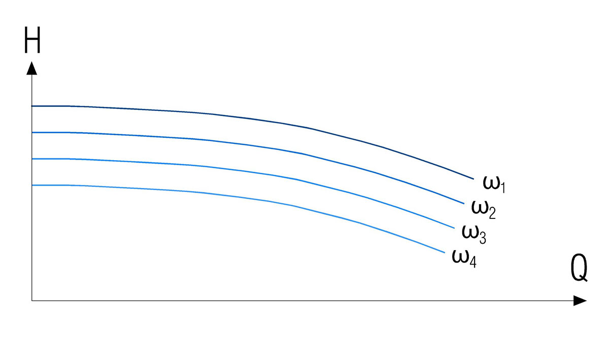
Pump drive curves for different rotational speeds
Let us now look at the applications of variable frequency drives in the particular case of water park installations:
Application of variable frequency drives in water park filtration pumps
Filtration pumps draw water from the pool, or from the compensation tank and pump it through the filter back into the pool. In a situation where the filter is clean (represented in the graph by the green driving characteristic curve), the operating point will be Pa (for Qa and Ha).
However, as the filter becomes dirty, the pressure drop it generates will be higher. Therefore, the driving curve will shift upwards (red curve). In this case, the hydraulic pump will have to overcome a higher head loss, so the flow rate it will pump will be lower, that is to say. the operating point will move to the left, to the Pb position (for Qb, Hb). After filter cleaning, it will return to the initial driving curve (green curve).
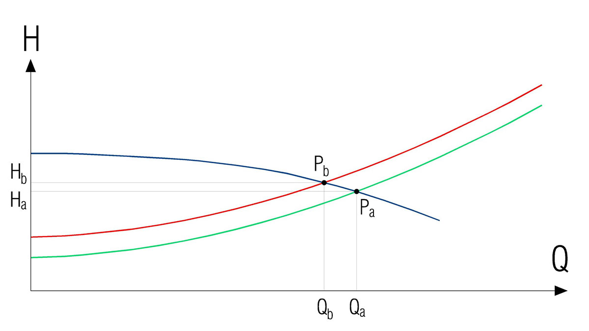
Operating points with clean and dirty filter
If we were to use a variable frequency drive in the situation described above, where the filter is dirty, we could increase the rotational speed of the hydraulic pump motor to keep the filtration flow rate constant.
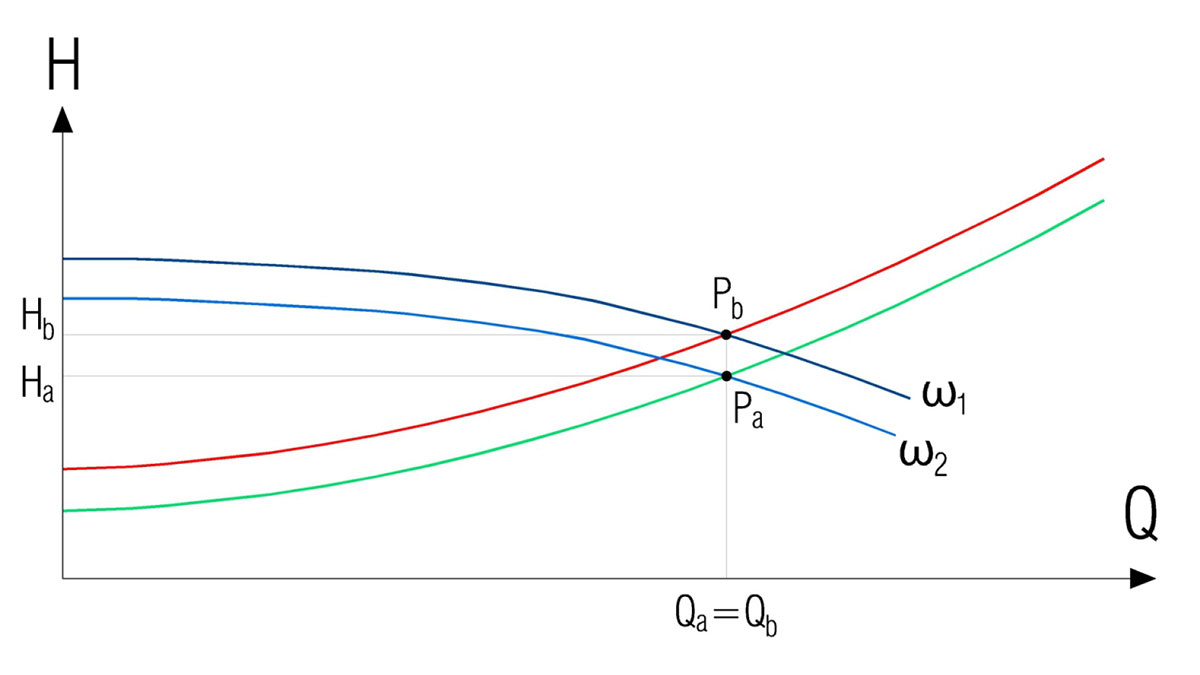
Operating points of a pump with variable frequency drive
In this case, we would change from the motor curve ω2 to the rotational speed curve ω1. In this way, we would pump at a higher head (Hb), with the same filtration flow rate (Qa=Qb).
In another case, for example when the water park is closed, we can reduce the filtration flow rate (from Qa to Qb), since it is not necessary, as there are no bathers, for the filtration to be so intense. Therefore, if we reduce the rotational speed of the hydraulic pump motor with the variable frequency drive (ω2), we will also reduce the impulsion flow rate (Qb).
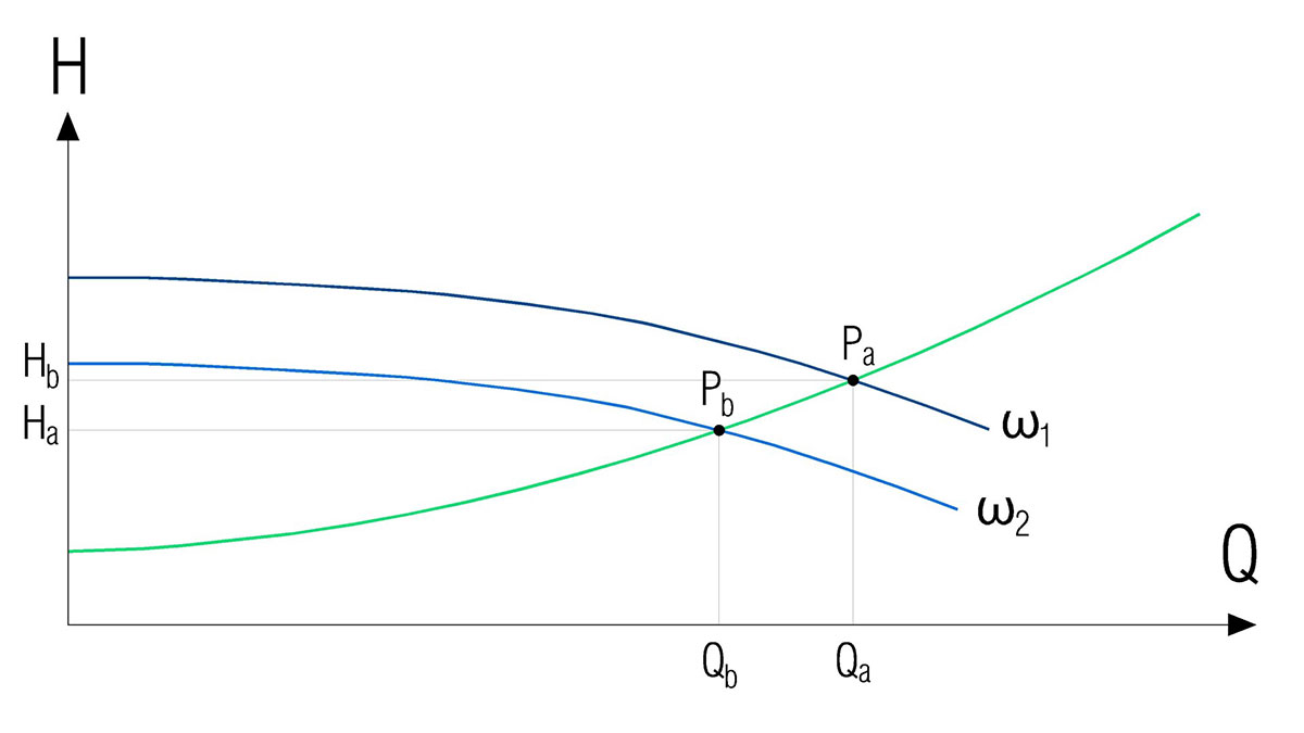
Variation of the filtration flow rate
On the other hand, if we use the hydraulic pump for emptying pools, the water does not pass through the filter, but is diverted beforehand. In this case, the curve of the pipe (orange curve in the graph) will be different from the one we had during filtration, since there will not be the pressure loss produced by the filter, in addition to the fact that the layout of the pipe, its length, its diameters and its accessories will be different from the first one.
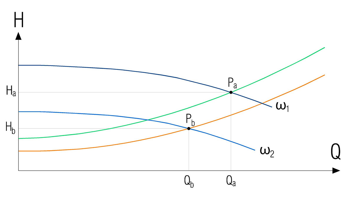
Variation of the operating point during emptying of swimming pools
As can be seen in the graph, we can decrease the rotational speed of the hydraulic pump motor (from ω1 to ω2) with the help of the variable frequency drive. As a result, we will have a new operating point for emptying and the pumped flow rate will be lower than the filtration flow rate, which may be convenient to avoid overloading the sewage network.
Other uses of variable frequency drives in water park hydraulic pumps
– Variable frequency drives in hydraulic pumps allow the optimal feed flow rate to be set for water slides, waterfalls, water curtains, spa and hydrotherapy elements.
-At the same time, they enable the pumps to change the rotational speed at start and stop times, so that these transitions are smooth and the phenomenon of water hammer is avoided.
In short, variable frequency drives allow the rotational speeds of hydraulic pump motors to be modified according to their optimum operating points for each function and situation, therefore extending their useful life and contributing to energy efficiency.
By Luis Llor, Senior Hydraulic Engineer in Amusement Logic’s Architecture Dept.


